What we did to rewire the US spec rear lights to be Euro spec
Rewiring Lights on our VW Camper Vans for UK use
This is a guide on how to modify the wiring on a US spec bus such that we have seperate flashing indicators of orange or amber colour – UK and Europe legal.
Rear time to complete the rear wiring change – about 1-2 hours depending on how much wiring is intact. Up front you will need a male / male joiner, at the rear you need 2 lengths of 1.75m cable, an assortment of crimps, tyraps and of course the light units and lenses.
Understand the Wiring Diagram for your Bus
Go to www.type2.com and find the relevant diagram for your bus, for example this is a typical 67 spec wiring diagram (click all of the picutes on this blog to get the bigger pictures) – this is one of their diagrams;

Under the Dash wiring modifications
Time : under 1 hour
Tools : screwdriver and light
Materials : male to male 1/4″ joiner
Its important to realise that the brake lights are the oddity here on US buses – the indicators are fine since they flash correctly when the brakes are not being pressed. The plan is to modify (or simplify) how the brake lights work and to remove their inter-action with the indicators.
Start looking or tracing what happens to the wiring to and from the brake light switch (J1);

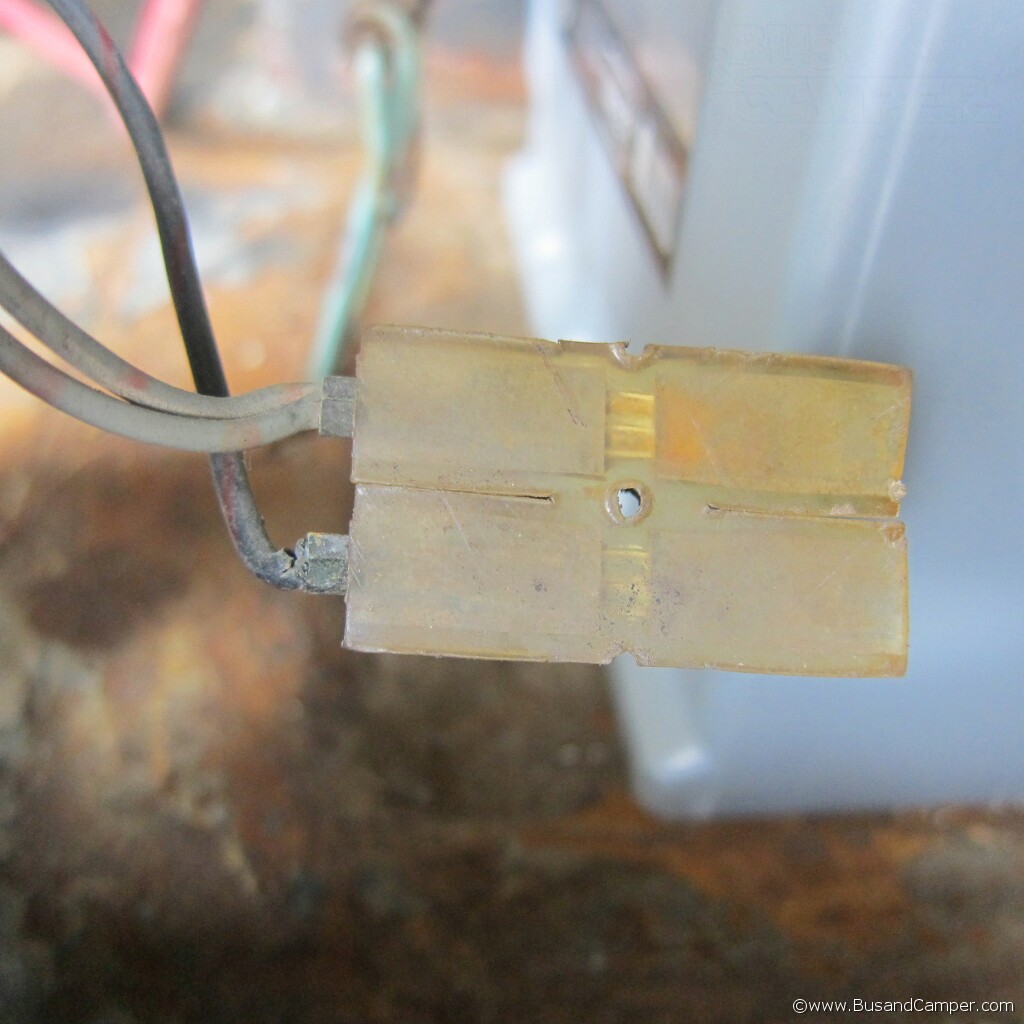
The pressure switch is a simple device – at around 15 psi or so the contacts should close. One side is connected to terminal 15 of the fusebox – switched with ignition, the other will find its way to the indicator stalk (early buses) or the 9 pin relay in 66 or so Buses. Here is a picture of the 9 pin relay in our 66 Bus with the black / red wire on terminal 54 circled;
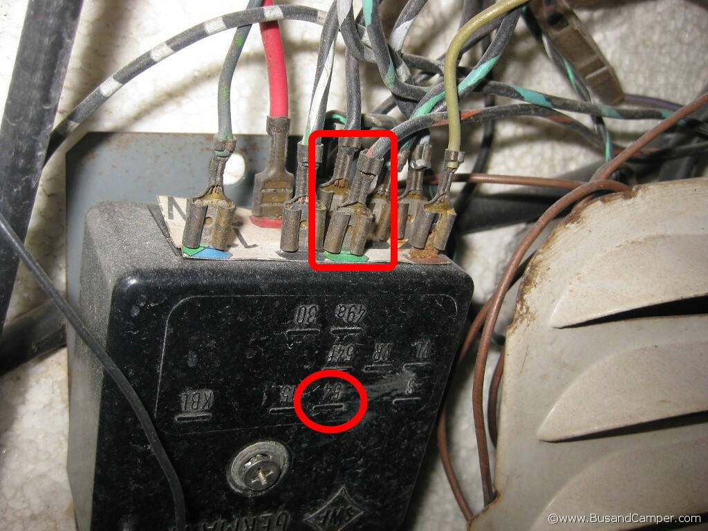
Earlier Buses, with the foot dip switch for example, may not have that complex 9 pin relay but the principal applies – the black/red wire from the brake light switch will find its way to the indicator stalk. Disconnect the black/red wire and insulate the indicator loom where it came from.
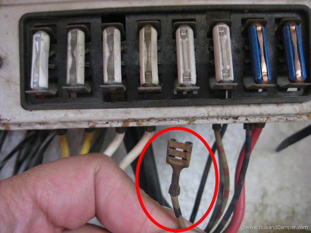
Basically this black/red wire needs to find its way to the rear of the Bus. Help is at hand – looking at the diagram we see two wires that run from the fusebox to the rear of the bus that do the job of sidelights – circled here;

Notice the two grey coloured wires – grey/black stripe and grey/red stripe – 2 seperate runs of wire for the rear lights in case one bulb goes you have another bulb. But anyway there are two 0.75mm sq (20 awg) wire to the function of powering the rear side lights (15W max) which is not near stressed for that size of cable. So we’ll use one of those rear light cables for the new brake lights – the grey/black is a single run from the fusebox to the left side side light.
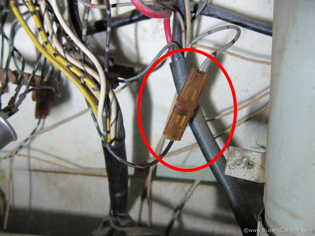
Disconnect thgrey/black from the fusebox terminal and connect it to the black/red wire – on earlier Buses there will already be a joiner on the black/red where it met the indicator stalk, but on later buses you need an equivalent part. This is the grey/black wire to use;
And this is the join made to the black/red wire from the brake switch;
Back of the Bus wiring modifications
Time : approx 2 hours
Tools : screwdrivers, wire cutters,
Optional : male/male 1/4″ joiners, male and femal 1/4″ crimps, new seals, tyraps
Must have : 2 x 1.75m 20awg wire in different colours
Replacement parts : Euro spec housings, Bulbs and Euro Lenses
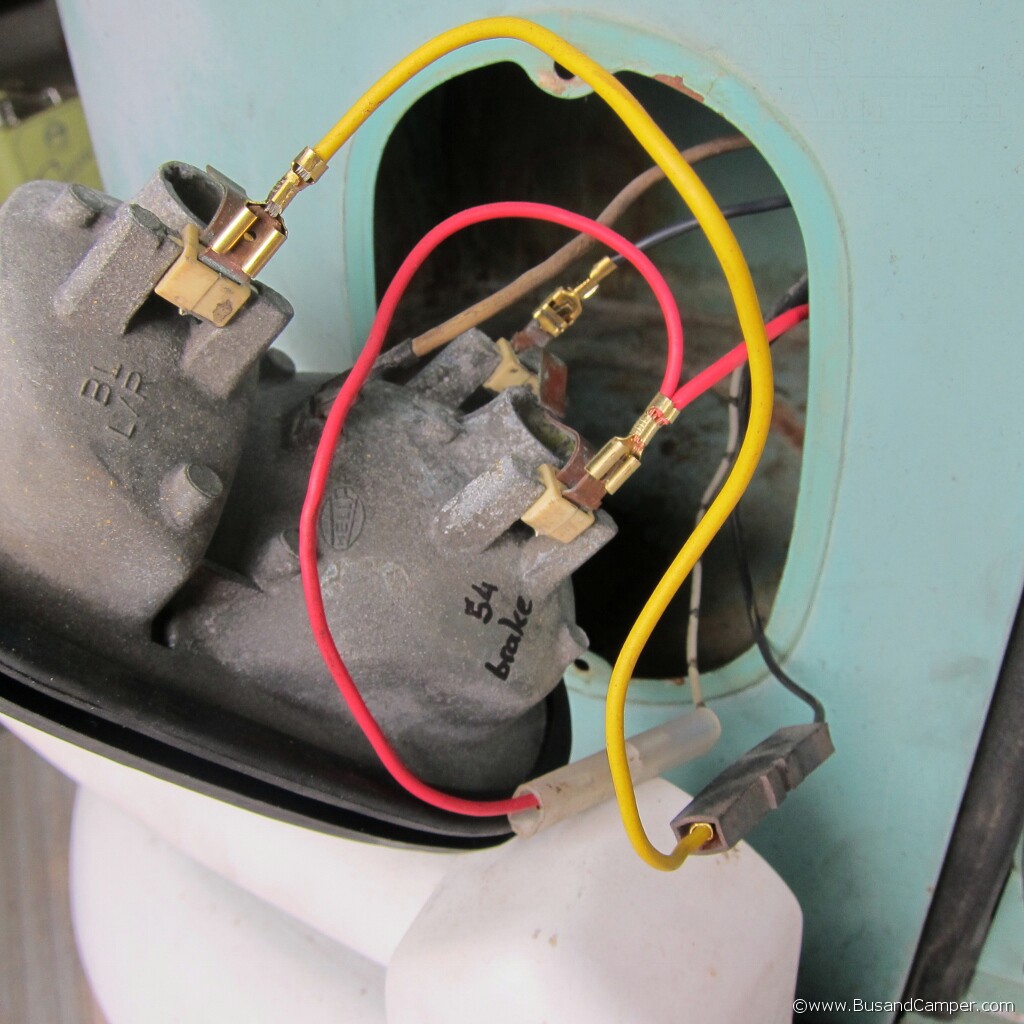
At the rear of the bus you will need to identify wire colours and how they are connected to the existing light housings. We had genuine Hella units which have male terminals on the back of the housings. Repro parts sometimes differ slightly with pigtails but usually always involve a 1/4″ crimp somewhere.
This is the wiring diagram at the rear lights, each housing will have 2 wires – grey wires for side lights and a black wires for brakes and indicators;
 .left..right.
This is the right side with the additional grey/red wire for the number plate light. The original housing is removed for this pic;
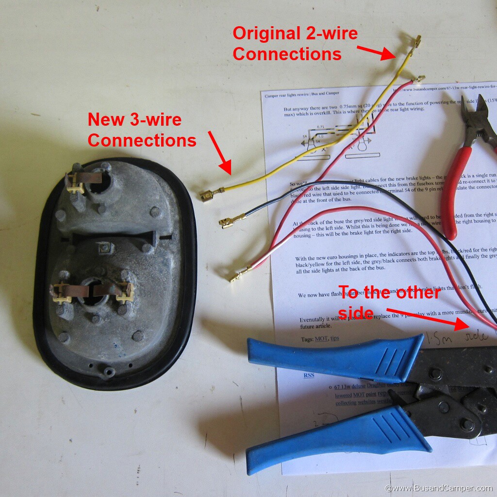
The hardest part is to make up the new wiring loom. You need to make 2 lengths of cable go from one housing to the other housing via the original cable run above the engine decklid.
Step 1 : Cut a 1.5m length of cable and crimp a female on one end,
Step 2 : On the opposite end use a short wire and crimp to make a Y connection.
Step 3 : Repeat steps 1 and 2 with another colour cable.
Step 4 : Find a 3rd colour cable for the short indicators.
This is an early Bus loom ready to be tyrap in place;
Basically the new loom will need to extend the grey/red to the side light on the left side, and the grey/black on the left side will need to be extended to connect to the brake light on the right side. Quick guide;
Grey/Red = Side lights
Grey/Black = Brake lights
Black = Indicators
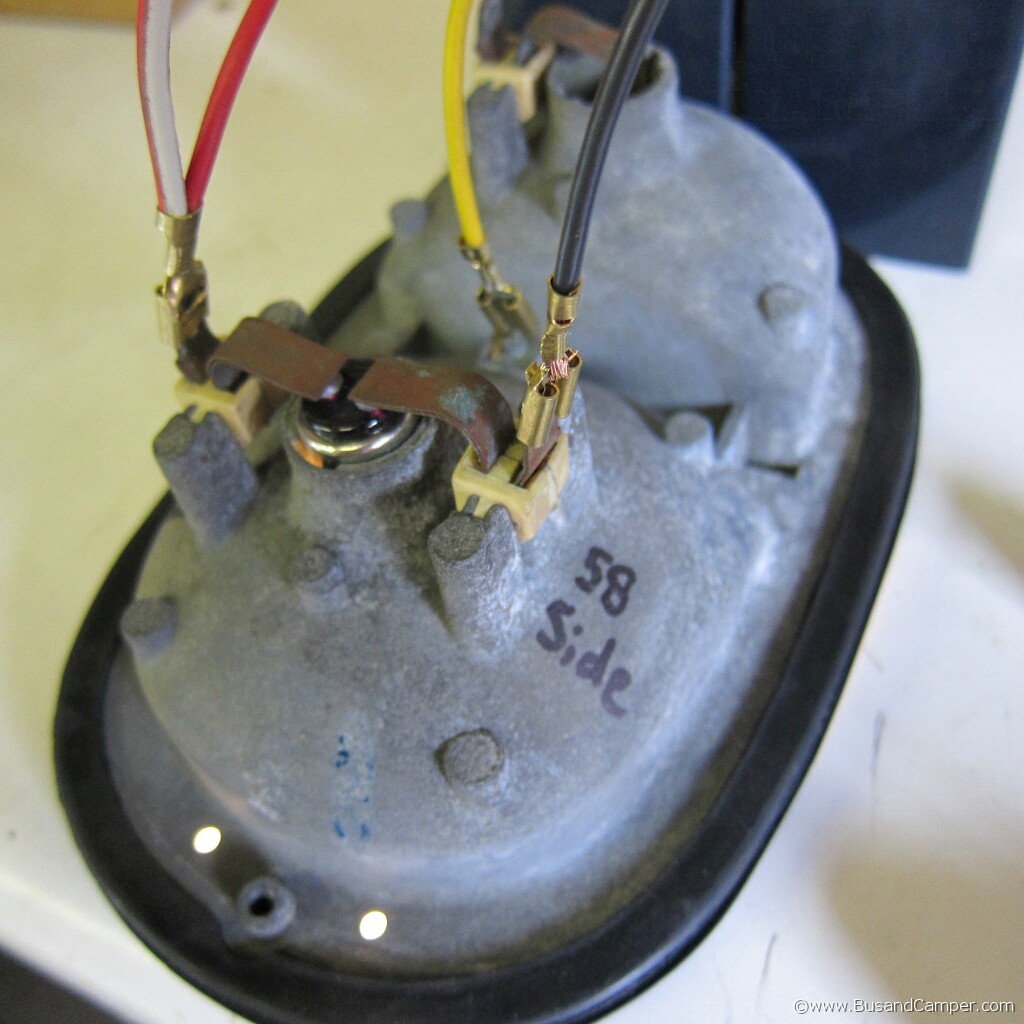
With the new euro housings in place, the indicators are the top bulbs, termial 54 is the brake light and terminal 58 the side light;
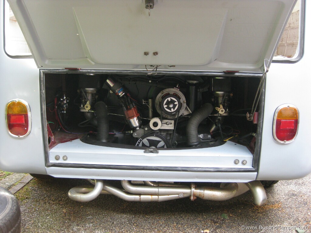
We now have flashing amber indicators and nice red brake lights that don’t flash. These are the higher quality hella rear lens with the painted in chrome outline effect. Installed with new quality seals the light output is excellent and there is little to no bleed from top to bottom;
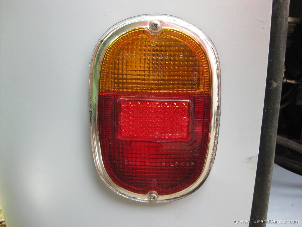
And both lights installed;